In general I try to buy server-class hardware for my home lab, primarily so that I could have IPMI / Remote access console for remote OS installation & troubleshooting. I recently got a new desktop and found myself with a Threadripper 1950x that would make an excellent addition to my server cluster. The one problem being it’s a desktop-class board, so it does not have any IPMI / remote access device.
I solved my problem with pikvm. It works wonderfully! Pikvm uses a raspberry pi with some additional hardware and software to interface with a system to control power & reset capabilities, as well as KVM functions with the ability to upload OS images and do OS installations remotely. The whole project cost me about $150 since I didn’t have some of the essential items for it. It could definitely be cheaper if I didn’t buy large packs of items or already had some electronics components.
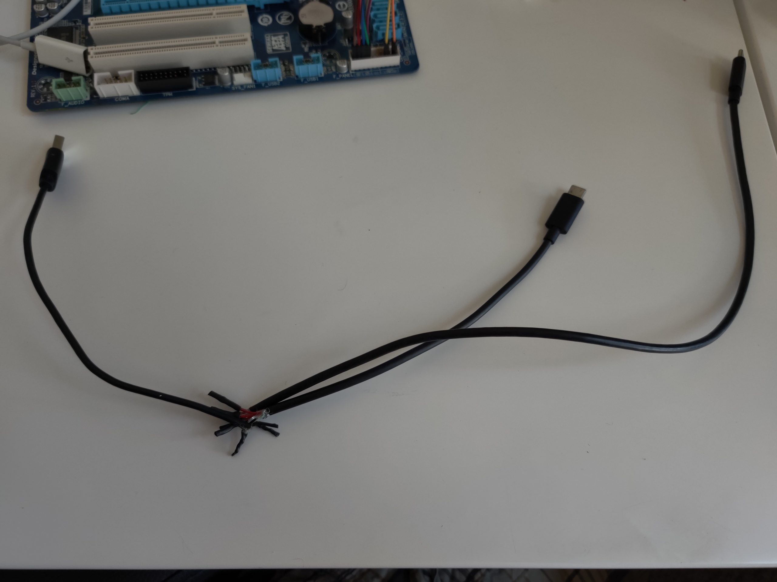
The process was straightforward as outlined on their github page. The only snag I ran into was creating the USB Y (split) cable. It did not work the first time, so I had to tear it all down and start again. One cable I used had more than 4 wires (3 red wires, 1 black, 1 green, 1 white, and 1 yellow.) When I re-assembled to include the yellow wire with the red and black, it all worked.
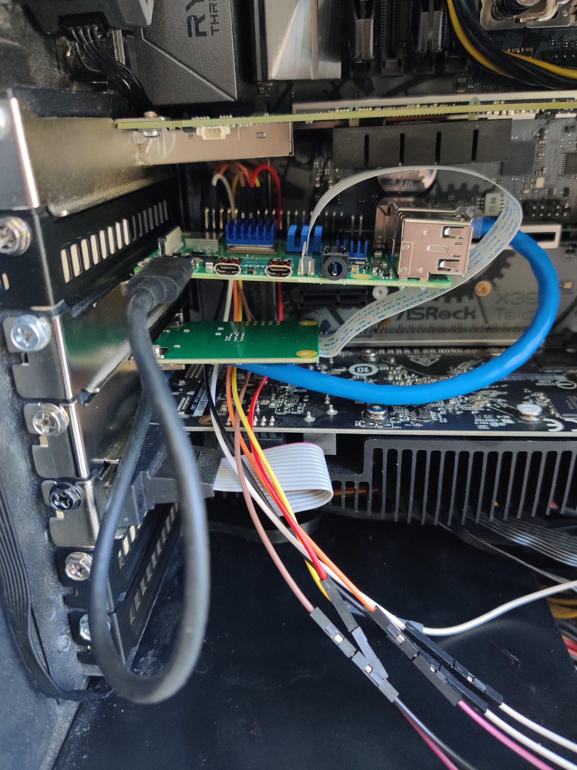
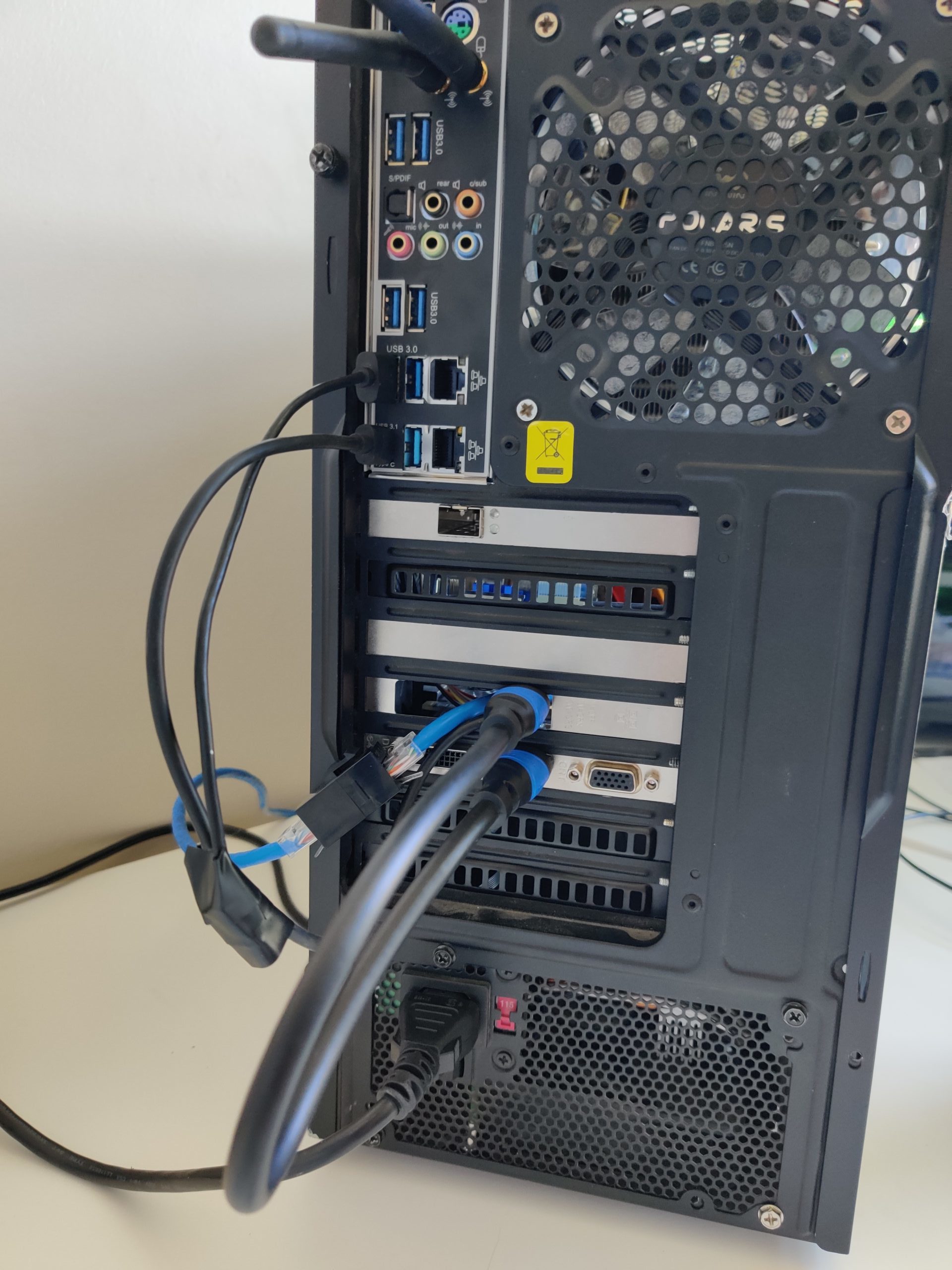
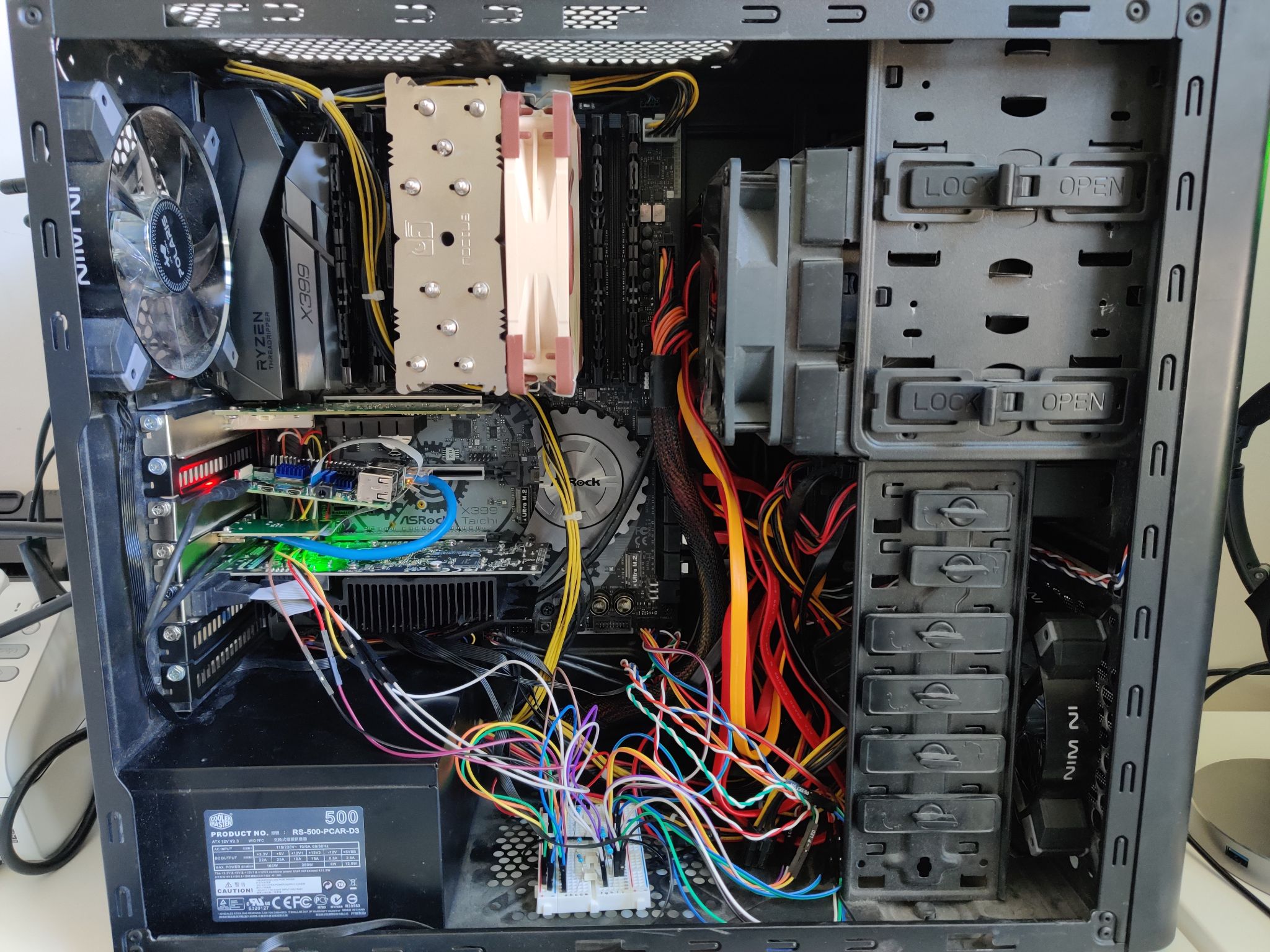
I scavenged the metal mounting bracket from some old networking adapter cards. With those I was able to mount the pi and the HDMI-in module to two standard PCI express card slots. I accidentally destroyed one of my SD cards while doing this so be careful if you try it! The PI is mounted at a slight angle so as to not damage the SD card. I had to mount it backwards (ethernet in the back) because I couldn’t get power to it otherwise (power port right up against the motherboard.) My workaround for this was to custom make a short length ethernet cord and use an RJ45 coupler on the outside of the chassis to provide an easy to access network port for the pi.
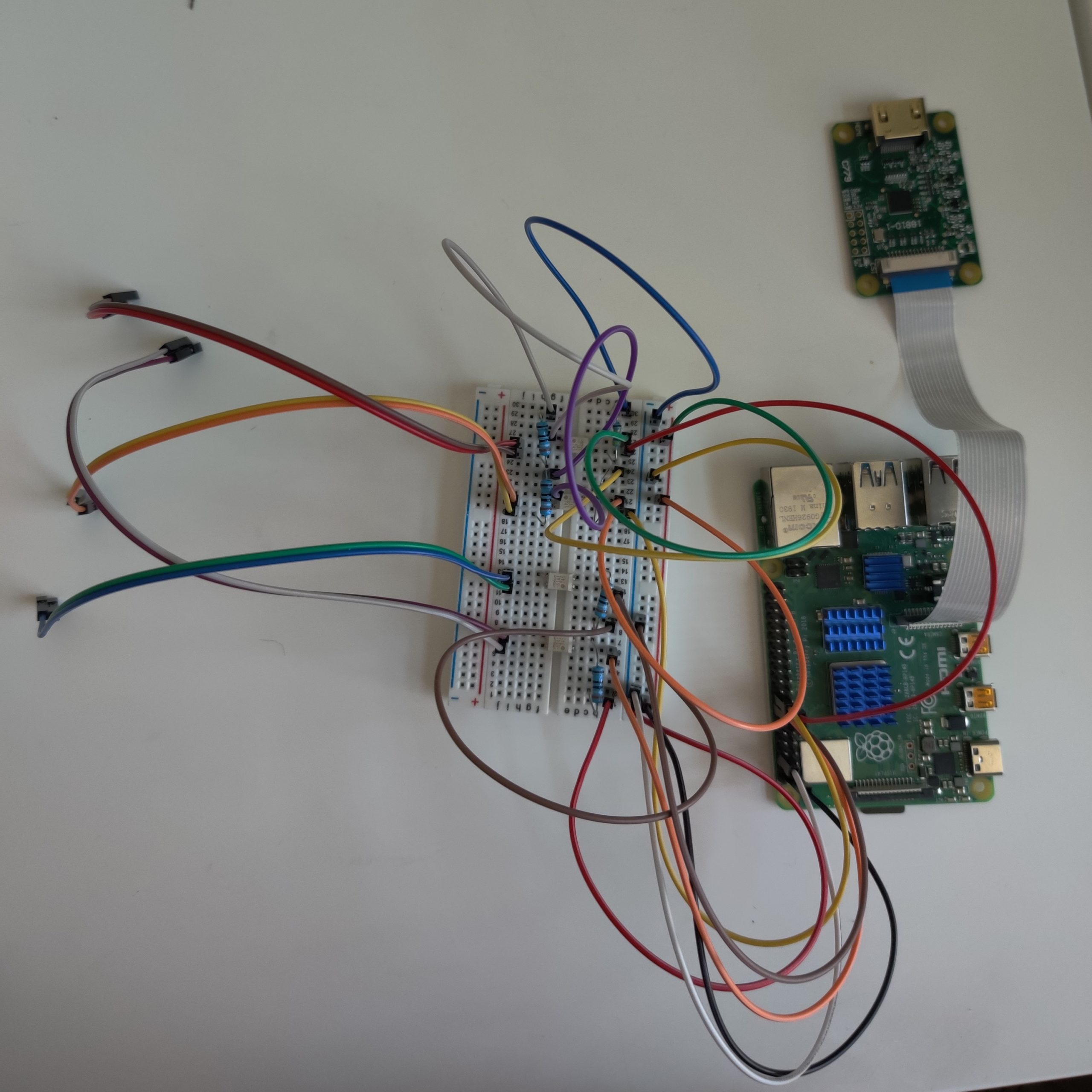
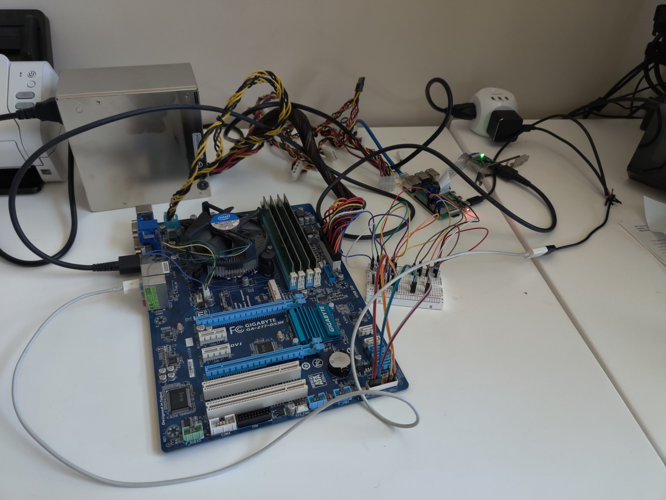
I wired the power & reset switch, as well as HDD and power LEDs in parallel so they would function with the chassis as well as with the KVM. To do this simply get some male-to-male jumper wires. On one end plug into the chassis wire, and on the other plug into the corresponding positive and negative slots right next to the ones going to the pi.
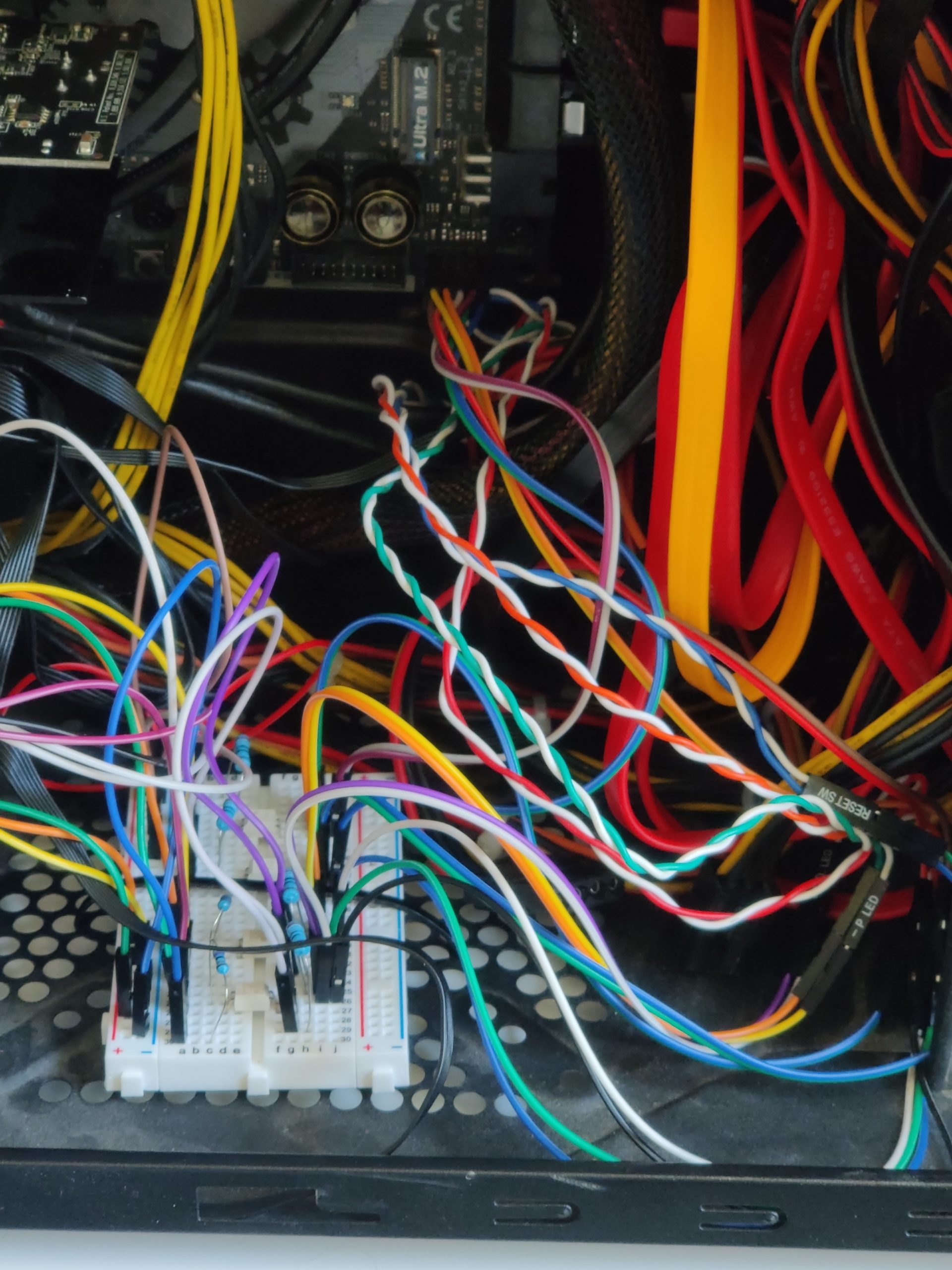
Broadboard pinout: https://github.com/pikvm/pikvm/blob/master/img/v2.png
USB split cable diagram: https://github.com/pikvm/pikvm/blob/master/img/v2_splitter.png
Parts list:
Raspberry Pi 4B 2GB edition: https://www.amazon.com/gp/product/B07TD42S27/ref=ppx_yo_dt_b_asin_title_o04_s00?ie=UTF8&psc=1
Raspberry Pi 4 headsink pack: https://www.amazon.com/gp/product/B07ZLZRDXZ/ref=ppx_yo_dt_b_asin_title_o02_s00?ie=UTF8&psc=1
Raspberry Pi HDMI in Module: https://www.amazon.com/gp/product/B0899L6ZXZ/ref=ppx_yo_dt_b_asin_title_o03_s00?ie=UTF8&psc=1
16GB Micro SD card: https://www.amazon.com/gp/product/B073K14CVB/ref=ppx_yo_dt_b_asin_title_o04_s01?ie=UTF8&psc=1
1 foot HDMI cable: https://www.amazon.com/gp/product/B00DI88XEG/ref=ppx_yo_dt_b_asin_title_o00_s00?ie=UTF8&psc=1
Breadboard 3 pack: https://www.amazon.com/gp/product/B077DN2PS1/ref=ppx_yo_dt_b_asin_title_o04_s01?ie=UTF8&psc=1
Breadboard Jumper Wires: https://www.amazon.com/gp/product/B07GD2BWPY/ref=ppx_yo_dt_b_asin_title_o04_s00?ie=UTF8&psc=1
Resistor Assortment Kit: https://www.amazon.com/gp/product/B0792M83JH/ref=ppx_yo_dt_b_asin_title_o04_s00?ie=UTF8&psc=1
390 OHM resistors: https://www.amazon.com/gp/product/B07QK9NFGT/ref=ppx_yo_dt_b_asin_title_o04_s01?ie=UTF8&psc=1
SSR relays: https://www.digikey.com/product-detail/en/G3VM-61A1/Z2100-ND/673290